In glass laser cutting, the typical quality-degrading issues are micro-cracks, chipping, and thermal stain/haze. This guide helps you quickly recognize the symptoms and systematically eliminate the root causes. For context and application examples, you can check the Glass sector page.
Most Common Issues and Their Symptoms
Micro-Crack: Hidden Risk, Delayed Fracture
It is the main trigger of fractures that are not visible immediately after cutting but appear during handling, assembly, or temperature changes. Symptom: Hairline striations detectable with a loupe at the edges; hazy regions along fracture paths.
- Typical causes: Excessive energy density, very small inner radius, insufficient hole–edge distance.
- Quick check: Visual light sweep around the edge, tape tests, sample thermal cycling (thermal shock).
Chipping: Losses in Aesthetics and Strength
Irregular small breakouts along the edge affect both the appearance and the mechanical strength of the part. Symptom: Pitting on the edge; roughness felt by fingertip.
- Typical causes: Improper fixturing, poor-quality optics/focus error, too many start–stop (pierce) points.
- Quick check: Reduce/distribute start points, verify with a focus card, add fixture cushioning (pads).
Thermal Stain / Haze / Burn Marks
Localized haze, discoloration, or linear streaks appear on the surface. Symptom: Patchy foggy look under bright light; accumulation of fume particles.
- Typical causes: Insufficient extraction/fume evacuation, low speed–high power combination, overly tight hatch spacing.
- Quick check: Increase hatch spacing, raise speed–lower power, improve airflow and optics cleanliness.
Quick Diagnosis Table
| Symptom | Possible Cause | Quick Fix |
|---|---|---|
| Micro-crack | High energy density, small inner radius | Defocus + speed ↑ + power ↓; increase radius; multiple light passes |
| Chipping | Fixturing error, focus offset | Fixture cushioning; calibration with focus card; distribute start points |
| Thermal stain/haze | Low speed–high power; weak extraction | Speed ↑, power ↓; hatch spacing ↑; adjust extraction/air blow |
Root Cause Analysis and Corrective Actions
Parameter Adjustments (Power/Speed/Defocus, Hatch Spacing)
To reduce energy density, a speed-up + power-down combination and a slight positive defocus are a safe starting point in most scenarios. Multiple light passes reduce micro-crack risk compared with a single deep pass. To choose the right configuration, you can review the solutions on the Laser Cutting Systems page.
- Hatch spacing (line spacing) → set to a medium–wide range based on heat accumulation.
- Reduce start (pierce) points and distribute them around the perimeter when possible.
- Increase inner-corner radius and hole–edge distances to safe thresholds.
Job Preparation: Fixturing, Cleaning, Masking
Use a cushioning layer under the glass plate to reduce vibration and local stress. Clean the surface before processing; use proper extraction and/or directed air to prevent fume particles from depositing. Masking film is useful on coated/mirror glass.
- Fixture: Evenly distributed support; extra cushioning around corners/reliefs.
- Cleaning: Residue-free materials for optics and glass surfaces.
- Masking: Heat-resistant, low-tack; define the removal procedure.
Hardware & Maintenance: Optics, Extraction, Cooling
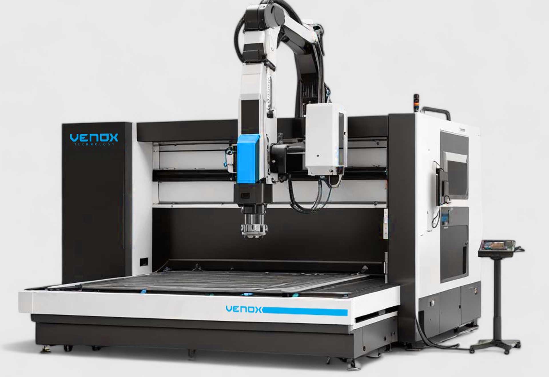
Optics/lens contamination can create hot spots at the focus. The extraction flow and direction must prevent fumes from entering the beam path. The cooling system (temperature, flow) should be monitored with alarm thresholds. For machine and accessory options, see the Laser Cutting & Marking Machines page.
- Optics maintenance interval: Quick check before each shift; detailed cleaning weekly.
- Extraction/filter: Monitor flow; replace early when filters clog.
- Cooling: Temperature/flow sensors and periodic fluid replacement.
Corrective Action Check-List (Rapid Field Application)
| Area | Step | Expected Effect |
|---|---|---|
| Parameters | Speed ↑, Power ↓, slight defocus, hatch spacing ↑ | Lower risk of micro-cracks and thermal stains |
| Preparation | Fixture cushioning, surface/optics cleaning, masking | Reduced chipping and surface staining |
| Maintenance | Lens/mirror cleaning, extraction/filter check, cooling upkeep | Improved stability and repeatability |
For additional guidance on configuration and process selection, refer to the Laser Cutting Systems and Glass sector pages.
Frequently Asked Questions (FAQ)
Why do micro-cracks usually appear later?
Micro-cracks may not be visible at first; they grow during handling/thermal cycling and lead to fracture. Reduce energy density, use multiple light passes, and follow safe radius/distance rules.
Is it possible to eliminate chipping completely?
Completely zeroing it out can be difficult; with proper fixturing, focus calibration, and post-edge polish/chamfer, the visible impact can be minimized.
What is the first setting I should check for thermal stains?
First check the air/extraction flow and optics cleanliness; then adjust parameters to speed ↑, power ↓, and hatch spacing ↑.
