
Laser Applications on Plastic and Interior Trim Parts
The automotive interior consists of dozens of components such as buttons, panel surfaces, displays, air vents, center console frames, steering controls, and door panels where driver and passenger interaction is intense. The plastic materials used in these parts must meet both aesthetic and functional requirements. Laser applications (laser marking and laser cutting) support these requirements with benefits such as speed, traceability, high contrast, and permanence. In this article, we will examine step by step how laser technology is positioned in plastic and interior trim components, what kind of advantages different laser sources provide, and how laser marking systems and laser cutting systems can be integrated into production lines. In addition, to analyze material behavior specific to plastics in detail, we will refer to the principles on the “laser on plastics” page and relate the sectoral context to the automotive page.
The Role of Laser Marking in Automotive Interior Trim Parts
Laser marking in interior trim parts covers a wide range of needs such as symbols, pictograms, function icons, part identification data, serial/model numbers, 2D codes (QR/DataMatrix), and user-facing warning texts. Ensuring that these markings are permanent, readable, and aesthetic directly affects user experience, safety, and traceability. Below, you can find the main application areas and critical points of laser marking for interior trim parts.
Which materials and surfaces?
Typical interior trim materials include polymers such as ABS, PC, PC/ABS, PMMA, PBT, PA6/PA66, PP (filled/unfilled), TPE, and TPU. Some are suitable for light-transmitting (backlit) designs; others are more suitable for producing high contrast on opaque surfaces. UV lasers provide fine details with low thermal impact (cold processing), while CO₂ lasers enable fast surface processing on organic-containing polymers. Fillers and additives (e.g., TiO₂, carbon black) significantly affect marking contrast.
Marking types and visual outcomes
Mechanisms such as color change, foaming, carbonization, and ablative removal occur depending on the formulation of the polymer. Matte-gloss contrast is expected in user interface icons; high opacity in safety warnings; and homogeneous light transmission in backlit buttons.
Backlit icons and “day-night” readability
Backlighting is a critical factor in center console, HVAC, and steering wheel buttons. The laser selectively removes the paint layer (ablation) to expose the light-transmitting surface underneath. Icon contours must be smooth, notch-free, and seamless. This approach ensures clear readability both day and night.
Traceability and 2D codes
Data such as part history, supplier, production line, cavity, shift, and quality controls are stored in 2D codes. Since laser marking is performed without chemicals and contact-free, it is suitable for mass production speeds. Verification of the codes in the production line (camera/verifier) and integration with MES/ERP completes the traceability chain.
UV, Fiber, and CO₂ selection criteria
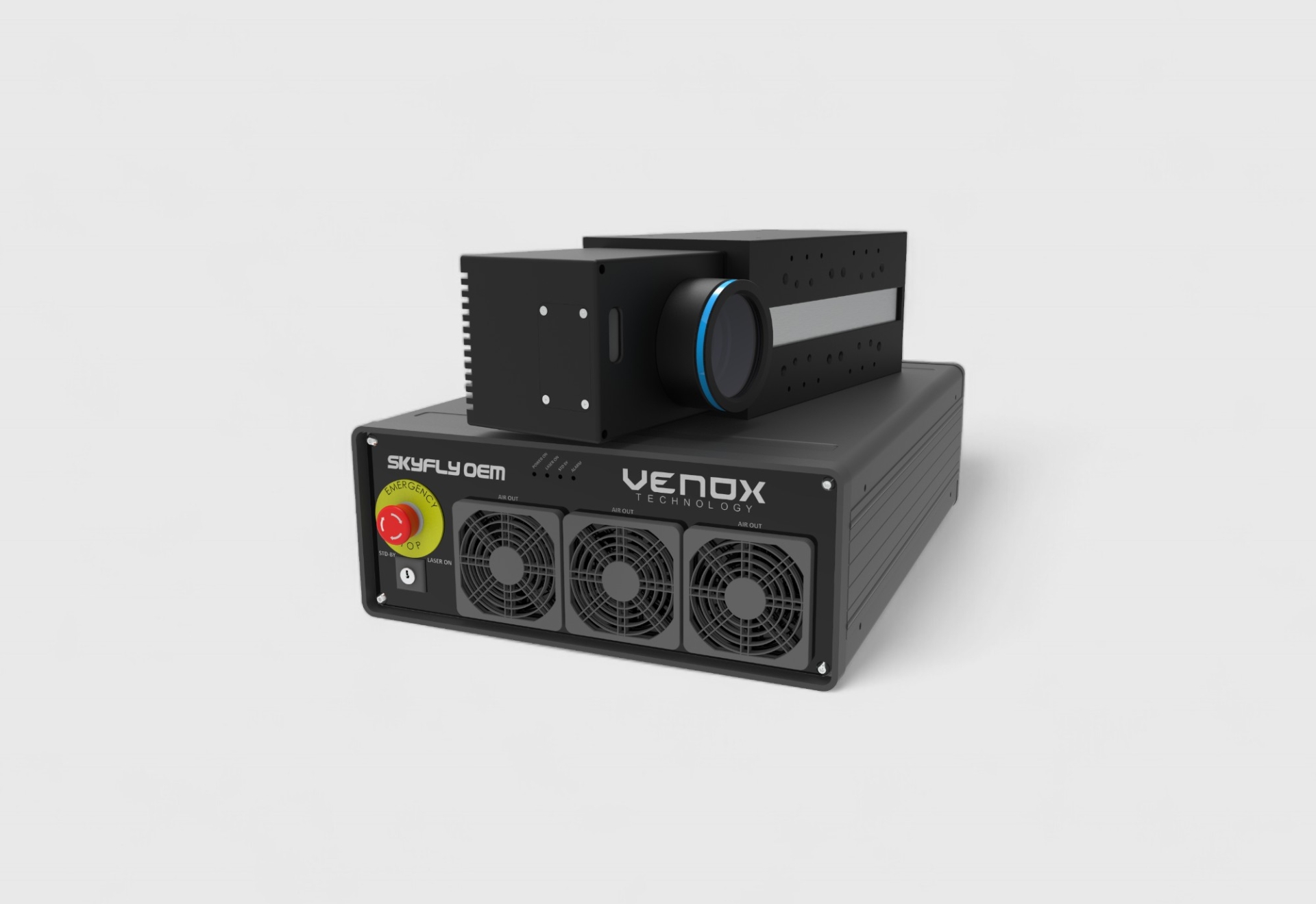
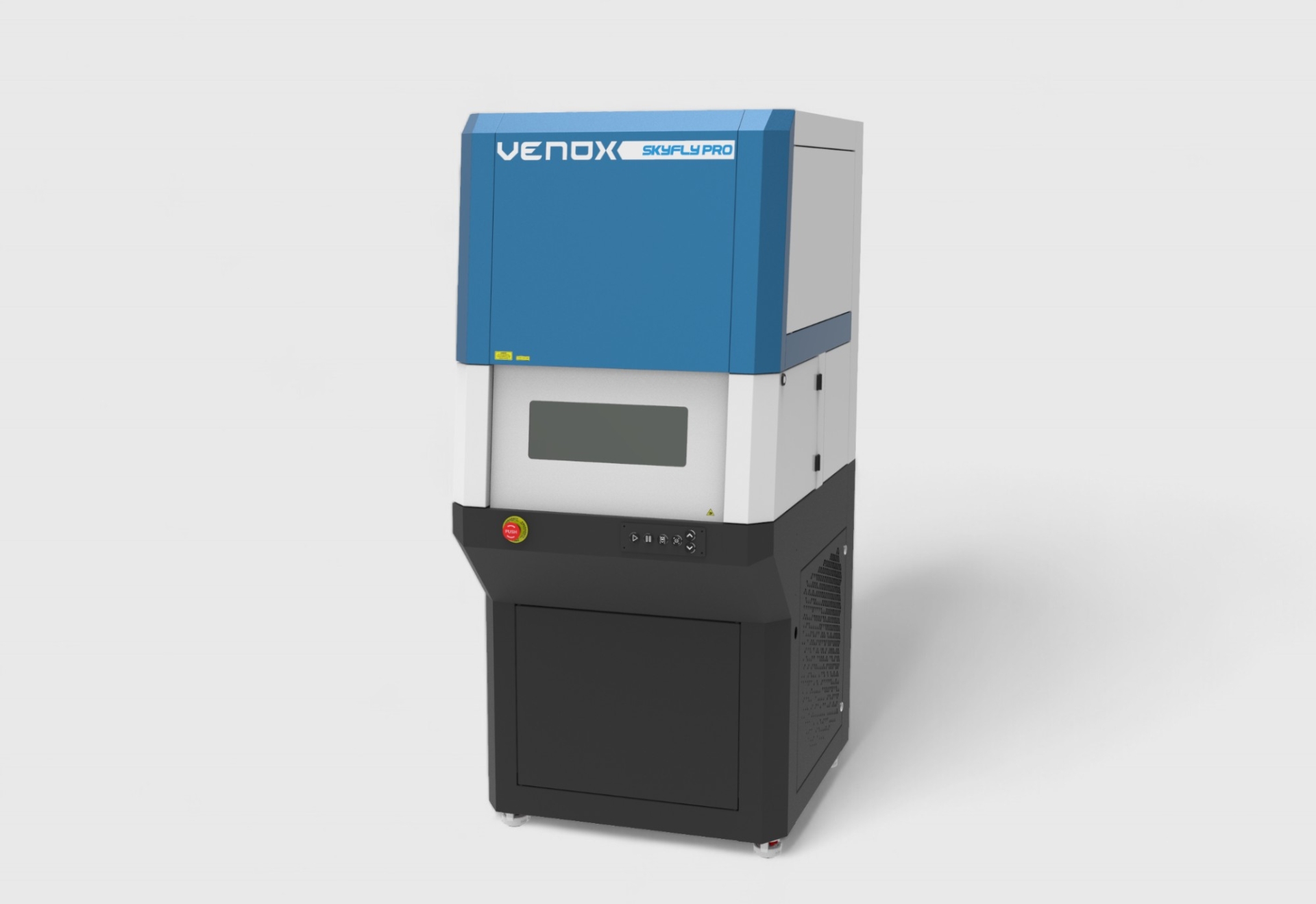
UV laser (355 nm) produces clean, sharp characters with fine details and low thermal impact on many types of plastics. Fiber laser can provide high speed and contrast especially on certain additive-containing polymers. CO₂ laser (10.6 μm) is preferred for fast surface processing and paint removal in organic materials. The goal is to select the correct source by balancing material formulation, desired contrast, speed, and cycle time. For suitable options, you can check the laser marking systems page.
Design rules and readability
In icon and font design, minimum x-height, stroke thickness, line spacing, and corner rounding should be defined. In 2D codes, cell size, module count, and “quiet zone” should be selected considering production tolerances. Trial markings (DOE) determine the optimum power–speed–frequency–fill spacing combinations.
Quality criteria and verification
Readability, contrast, edge sharpness, absence of defects (replication marks, shadowing, burn halos, etc.), and repeatability are tracked. During production, 100% inspection with cameras and, when necessary, automatic adjustment corrections (closed-loop) are recommended.
Environmental and operational benefits
Lasers do not require consumables; they reduce solvent/paint consumption and waste. Since the process is contact-free, costs such as fixture wear and tip consumption are eliminated. “Plug-and-play” stability and low maintenance requirements shorten planned downtimes.
Laser Cutting in Plastic Parts: Quality, Speed, and Flexibility
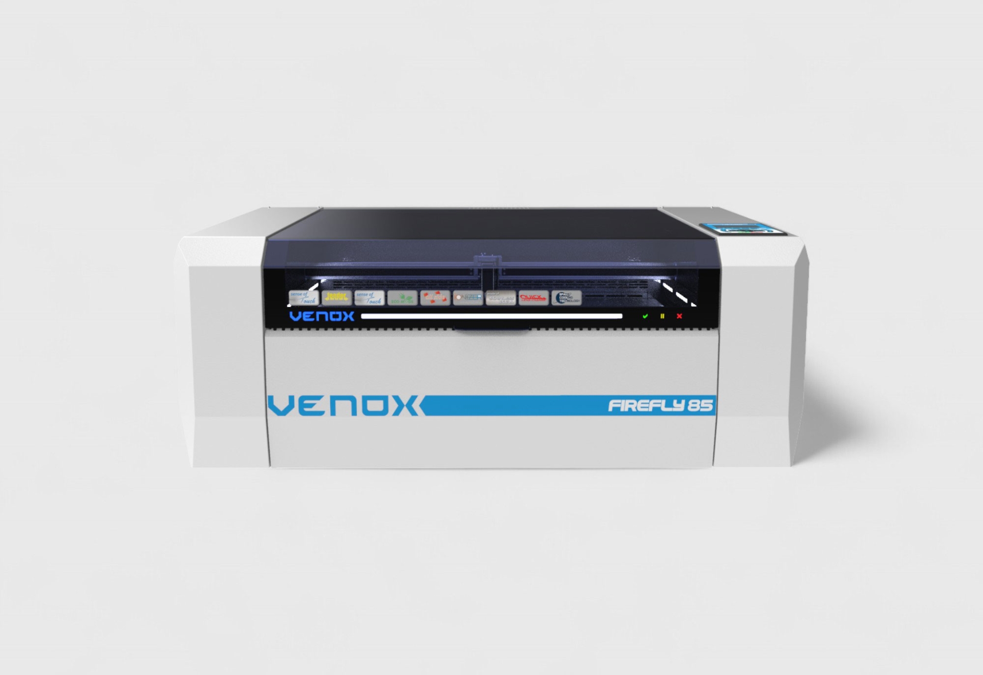
Laser cutting in interior trim components stands out in applications such as diffusers, decorative coatings, light guides, thin film/foil layers, gaskets, fabric/upholstery parts, and acoustic perforation patterns. High speed and repeatable quality reduce the constraints of multi-part molds or blade grinding. The laser cutting systems page can be referenced for appropriate system and optical combinations.
Cutting edge quality and thermal effect
The goal in cutting is to achieve a smooth edge, minimum burr, and narrow HAZ (heat-affected zone). In thin films and visible surfaces, single-pass CO₂ cutting is expected; low yellowing in polycarbonate and acrylic; and clean lines without fiber pull in textiles. Parameters are optimized according to material thickness and optical spot size.
Acoustic perforation and invisible hole patterns
In door panels, steering wheels, and roof fabrics, microscopic hole patterns, often barely visible to the eye, are applied to enhance acoustic performance. The laser allows easy adjustment of pattern density and placement through CAD, offering adaptable solutions for different NVH targets.
Paint removal and multilayer structure processing for backlit
In backlit designs, the layered paint structure is selectively removed by laser. Thus, the light emitted from the lower layer becomes visible in the form of an icon or contour. In multilayer films, a dedicated parameter set (power, speed, scan count) is defined for each layer to ensure selective processing “without damaging the underlying layer.”
Process window and trial plan
The cutting parameter space is defined by power, speed, scan count, hatch spacing, and focus offset. Through a systematic DOE (Design of Experiments), the optimal set for each material/thickness is determined to achieve edge smoothness, minimal whitening/yellowing, shrinkage, and dimensional tolerance goals.
Fixturing and part repeatability
Vacuum tables and light clamping fixtures are used for thin and flexible materials, while rigid parts are supported with reference pins and multi-part fixtures. The optical field (F-Theta lens) and working area are planned to process multiple parts within the same cycle (panelization).
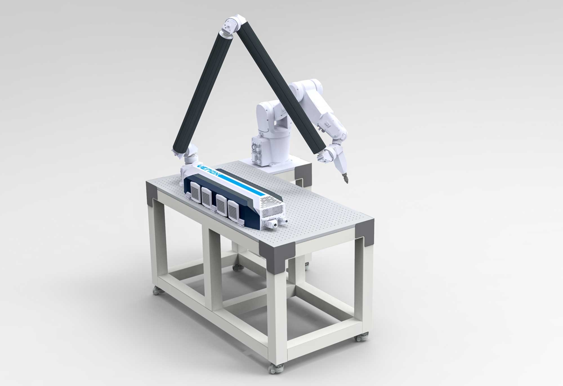
Integration into production lines
Cutting/marking can be combined in “parallel station” setups with conveyors, rotary tables, and pick-and-place systems. Automatic camera positioning, 2D code verification, and robotic loading/unloading balance the CT (cycle time). Integrated solutions can be explored on the marking and cutting product pages.
Safety and ergonomics
Closed cabin designs, safety viewing windows, and interlock systems ensure operator safety. Smoke and particle extraction contribute to keeping optics clean and maintaining environmental conditions. User authorization in the operator panel and software interface reduces error risks.
Total Cost of Ownership (TCO) and Return on Investment (ROI)
The non-consumable nature of lasers reduces the need for periodic purchases of tools/blades. Shorter process times, automation compatibility, and reduced quality defects provide a measurable ROI across the line. Pilot production and part-based time studies are recommended before initial investment.
Example application scenarios
- HVAC and multimedia console: Backlit icon ablation + UV marking for sharp contours.
- Steering wheel control buttons: High-contrast pictograms; equal readability day and night.
- Door inner panel: Acoustic perforation and decorative thin film cutting.
- Center console frame: Smooth edges with CO₂ cutting in thin-walled PC/ABS frame.
- Part traceability: Post-injection 2D code marking and inline verification.
Material–laser matching summary
As a general rule; UV provides clean processing with low heat effect on most plastics, CO₂ offers speed in organic content and paint removal, while fiber delivers high contrast and speed depending on plastic types/additives. The final choice is clarified by sample trials, target cycle time, and surface expectations. To explore laser behavior on plastics in detail, see this guide.
Software, data, and process control
To reduce operator errors; job queue, product recipe, barcode–data retrieval, lot number automation, and “one-touch change” functions are recommended. Automatic alignment with a camera and 2D code verification can be combined in the same station.
Sectoral context and compliance
Compliance with safety and quality-focused standards in the automotive industry makes permanent and readable markings mandatory. Laser technology meets these requirements at mass production speeds. For examples and approaches focused on interior trim, visit the automotive page.
Procurement and scalability tips
- Need definition: Part list, material types, annual quantities, and CT targets.
- Samples and DOE: A small trial matrix for each material/coating.
- Integration: Line setup with conveyor/rotary table/robotics and camera–verifier.
- Software: Recipe, user authorization, data collection, and traceability integration.
- Service and training: Operator/technical team training and spare parts–optics maintenance.
Conclusion: Clarity, Speed, and Traceability with Laser in Interior Trim
Laser marking and laser cutting in plastic and interior trim parts bring together aesthetics, function, and traceability. With the right laser source selection (UV–CO₂–fiber), a well-defined process window, and inline verification, high-contrast, permanent, and repeatable results are achieved. An integrated approach enhances product quality while reducing overall costs. To evaluate the most suitable solution for your application, you can explore the marking systems and cutting systems pages; check this guide for laser behavior in plastics; and refer to the automotive page for sectoral requirements.
