
Laser Glass Cutting: Industrial Use, Technology Selection, and Step-by-Step Application Guide
Fundamentals of Laser Glass Cutting
Glass Processability with Laser: Physical Basis
Due to its amorphous structure and high surface hardness, glass is suitable for laser cutting compared to conventional machining. The laser beam generates localized heat energy on the glass surface; this energy triggers thermal stress and controlled crack propagation mechanisms, producing cutting or guiding scratches (scribing). Especially CO2 lasers with a 10.6 µm wavelength are widely preferred in glass cutting and separation processes, as glass absorbs them better. Ultrafast (ps/fs) lasers minimize microcracks and chipping, providing much cleaner edge quality.
Which Laser Source?
- CO2 laser (10.6 µm): Industry standard for cutting/splitting materials such as flat glass, mirrors, and borosilicate glass. Thermal effect is controllable; with correct parameters, microcracks and chipping are reduced.
- Ultrashort pulse (ps/fs) laser: High precision, low heat-affected zone (HAZ), and superior edge quality. Ideal for thin glass, display glass, and optical components.
- Fiber laser (1.06 µm): Limited absorption by glass; generally used for marking and coating/film removal rather than direct cutting. Effective in combined tasks with metal frames/accessories.
Cutting Types: Thermal Separation and Scribing
The thermal separation approach is based on heating along the laser line and immediately followed by controlled cooling (e.g., air/cold gas) to guide the crack. Scribing creates controlled micro-damage on the surface, enabling clean separation by mechanical breaking. Part thickness and edge quality requirements determine the choice between these two methods.
Precision and Edge Quality
Main parameters affecting edge quality: beam diameter, focal position, scanning speed, pulse energy/peak power, and multi-pass processing strategy. For thin glass, a single pass may be sufficient, while for thicker glass, multiple passes and spiral or multi-line strategies improve results.
Safety and Material Integrity
Glass is sensitive to thermal shocks. Sudden temperature gradients may cause undesired cracks. Therefore, the process must be stabilized with preheating, controlled cooling, and proper fixturing. During operation, laser safety rules such as protective eyewear, fume extraction, and beam shielding are critical.
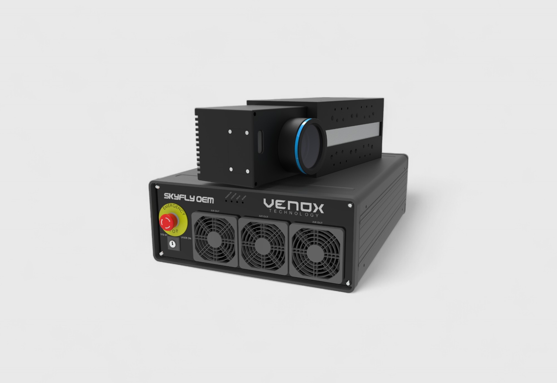
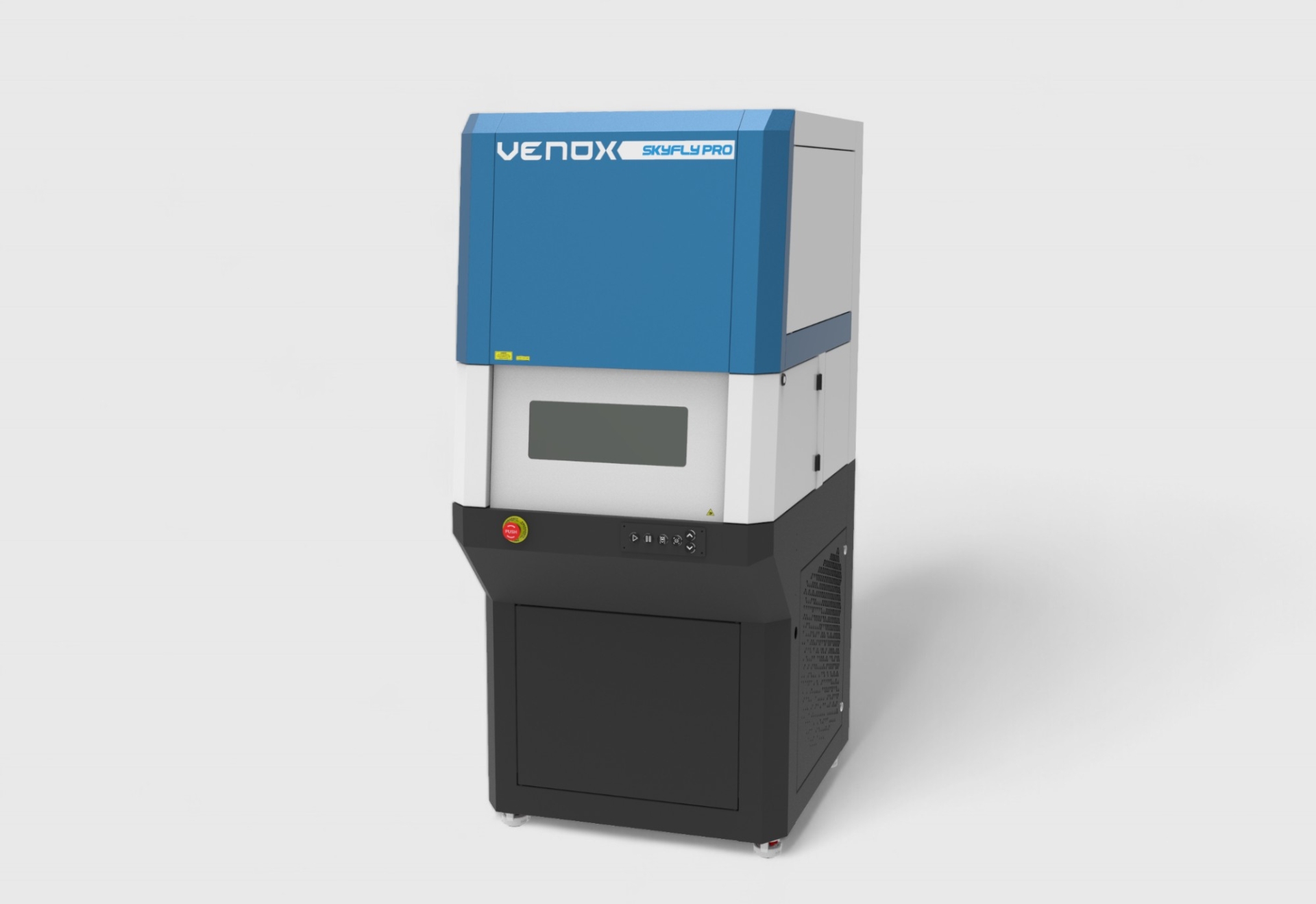
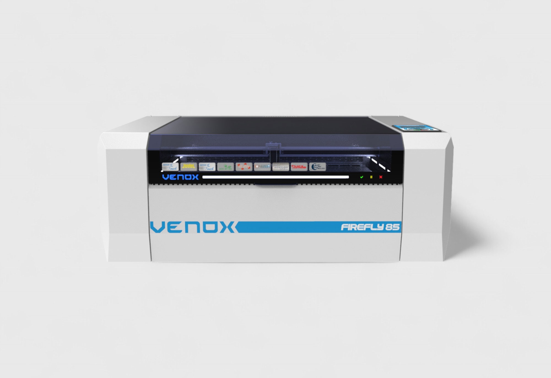
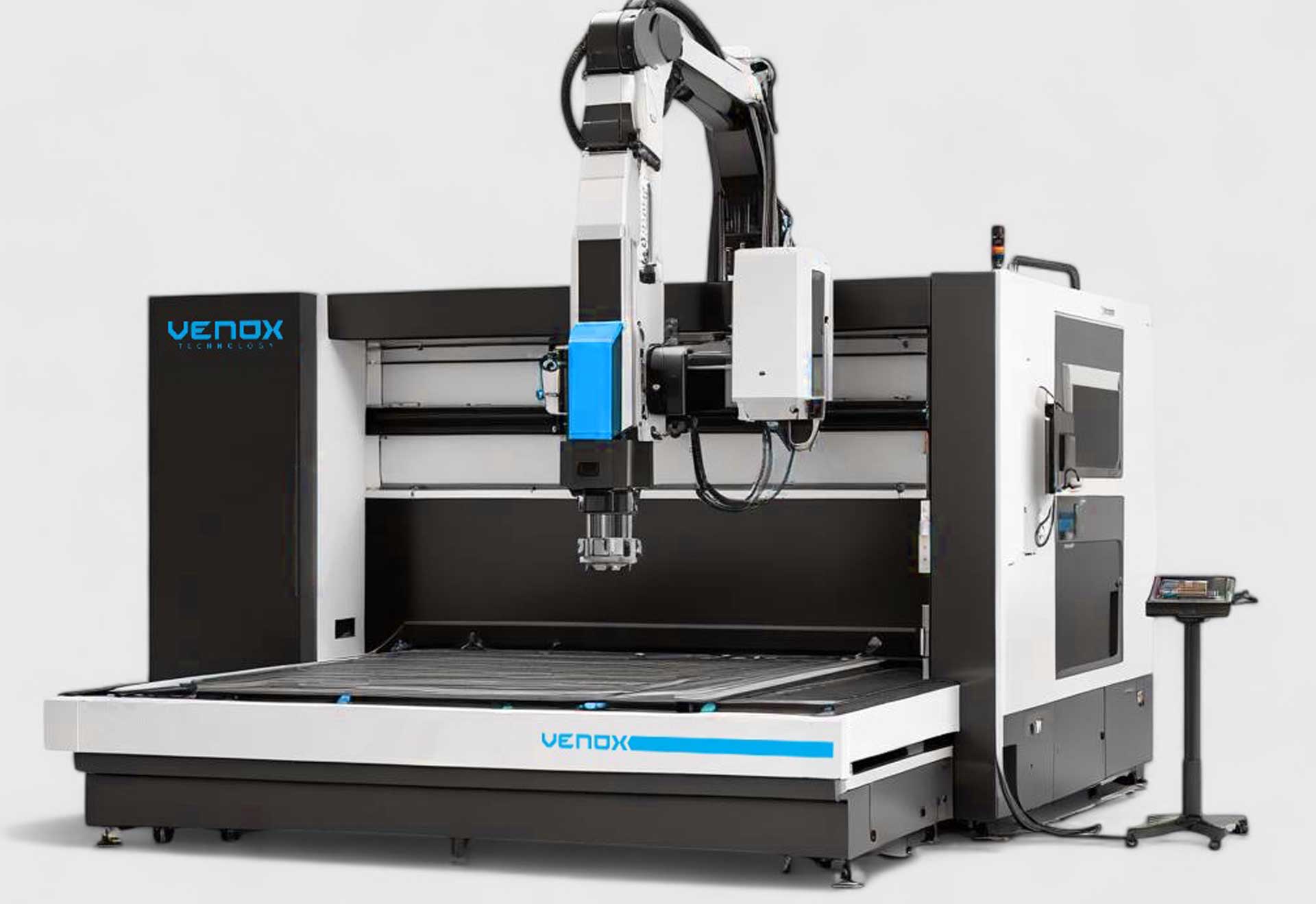
Machine and Automation Infrastructure
In industrial production, laser cutting systems are offered together with motion control (X-Y gantry/SCARA), vision systems (edge/mark detection), and cooling/exhaust components. Control software integrated into CAD/CAM workflows optimizes cutting paths, increases repeatability, and reduces scrap rates.
Application Steps and Parameter Optimization
Step 1: Material and Thickness Analysis
The type of glass (float, borosilicate, tempered, coated/uncoated) and thickness determine wavelength selection and energy density requirements. For 1–3 mm thin glass, thermal separation is fast; for thicknesses of 5 mm or more, multi-pass or two-step strategies (scribing + breaking) may be preferred.
Step 2: Beam Profile Selection
To ensure homogeneous energy distribution along the cut line, proper spot size and focal length are selected. Gaussian profile provides high accuracy in thin glass, while for thick glass, a top-hat (nearflat) profile may offer advantages. Ramp-up/ramp-down (power softening) is applied at entry/exit points.
Step 3: Energy, Speed, and Number of Passes
- Laser power/pulse energy: Insufficient power extends cutting times; excessive power increases the risk of microcracks and chipping.
- Scanning speed: Higher speed means less thermal effect; lower speed creates deeper effect. The goal is a balance of adequate penetration + low HAZ.
- Pass strategy: Multiple shallow passes improve edge quality compared to a single deep pass.
Step 4: Thermal Management and Cooling
Blowing cold air/nitrogen immediately behind the cutting line improves crack guidance and balances internal stresses in the glass. If necessary, a fine water mist is applied to reduce microstructural damage and dust adhesion.
Step 5: Fixturing and Vibration Control
Stable support is provided with a flat and stress-free bed, vibration-absorbing pads, and a vacuum table. For coated glass, the coated surface must be oriented correctly considering optical reflections and heat accumulation.
Step 6: Path Planning and CAD/CAM
Using fillets (rounding) at corners and small tabs (holding bridges) prevents part drop-off and edge chipping. In inner cuts, the principle of inside first, then outside contours minimizes scrap. Cutting-marking combinations accelerate production in a single setup.
Step 7: Coating/Film Presence
Low-E, mirror, or decorative coatings alter absorption behavior. If necessary, laser marking systems are used first for coating removal (masking/ablation), followed by the main cutting.
Step 8: Edge Finishing and Cleaning
After laser processing, micro-burrs and dust residues are removed with ionized air and HEPA vacuum. For applications requiring high optical quality, light flame polishing or chemical washing may be necessary.
Step 9: Quality Control and Traceability
Edge roughness (Ra), crack length, and HAZ width are measured. Camera-assisted vision inspection automates crack/break detection. Traceability is ensured by adding lot and date codes per part with laser marking.
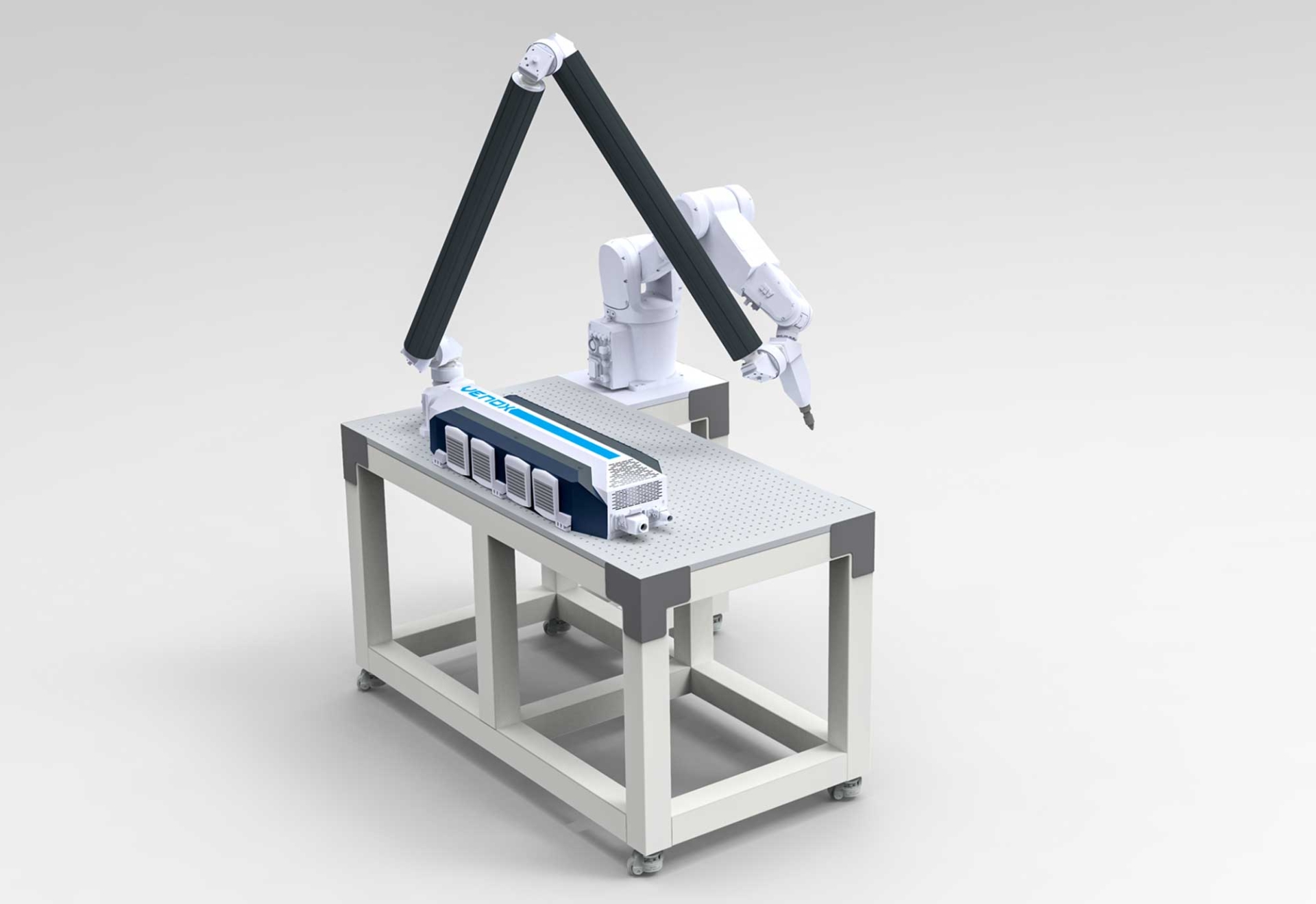
Step 10: Integration into Production Line
For high volumes, conveyors, robot arms, and palletizing enable automation. In MES/ERP integration, job orders, batch numbers, and process parameters are recorded. Industrial laser cutting systems come with I/O and industrial protocols supporting this integration.
Tips by Glass Type
- Float glass: Standard cutting; thermal separation is efficient.
- Borosilicate: Lower expansion; crack propagation is more controlled, requiring re-adjustment of power/speed.
- Tempered glass: Pre-stressed; conventional cutting is not possible. Cutting must be done before tempering, or special fs-laser methods are required.
- Coated glass: If ablation is required, remove coating first; otherwise, place the coated side down.
Typical Parameter Ranges (Sample Approach)
Values vary depending on thickness, glass type, and machine; however, for a sample CO2 scenario:
- 1–2 mm glass: 20–60 W optical power, 300–800 mm/s speed, single/double pass.
- 3–4 mm glass: 40–100 W, 150–500 mm/s, 2–4 passes + cold air.
- 5 mm+ glass: 80–150 W, 80–250 mm/s, multiple passes + scribing-assisted separation.
Note: Values depend on machine and optical configuration; optimization with DOE (Design of Experiments) on samples is always recommended.
Edge Quality and Fracture Strength
Edge strength is related to the control of microcracks. Multi-pass shallow cuts, edge polishing, and controlled cooling reduce fracture risk in stressed applications (e.g., hinged glass parts).
Efficiency and Cost
Laser glass cutting eliminates mold and tooling costs, providing flexibility for small/medium batches. Digital workflow reduces setup time and allows quick adaptation to product variations. Scrap rate is low, repeatability is high.
Application Areas
- Furniture and decoration: Mirrors, showcases, shelves, decorative glass panels.
- Electronics/Display: Thin display glass, lens covers, sensor windows.
- Automotive: Interior trim glass parts, dashboard glasses (coating sensitivity is important).
- Architecture: Facade glass (coating strategies and large-format processing).
- Laboratory/Optics: Borosilicate tubes, slides, optical windows.
Checklist for Machine Selection
- Laser type and power range (CO2 / ps-fs).
- Working area, motion resolution, and speed.
- Vision system, focus tracking, and dynamic focusing.
- Cooling, exhaust, and filter system capacity.
- CAD/CAM compatibility and workflow software.
- In-line integration (I/O, fieldbus) and safety class.
When evaluating these criteria, considering cutting-marking combination machines and marking units for single-station production helps reduce total cycle time.
Sample and Process Validation
Before mass production, edge roughness, curvature, crack propagation, visual quality, and mechanical strength tests are applied on sample series. Once the parameter window is determined, an SOP is prepared and operator training is conducted.
Maintenance and Continuity
Periodic cleaning of optics, alignment control, exhaust filter maintenance, and monitoring of the cooling system are essential for stable power output and repeatable quality. Maintenance schedules should be structured weekly/monthly depending on production intensity.
Advanced Topics: Microstructure Engineering
With ultrashort pulse lasers, multi-axis scanning and volume modifications such as buried waveguides offer new opportunities in optical device and sensor applications. Such advanced processes require stricter temperature and vibration control.
Internal Linking Strategy
For on-site SEO, adding links from this page to related product groups such as laser cutting systems, laser marking systems, and cutting/marking machines directs users to decision pages and increases navigation depth.
